Elevation Design
Table of contents
- Overview
- Elevation Design Inputs
- Elevation Design Modes
- Create Network Profile View
- Workflow Examples
Piping Engineer provides multiple elevation design capabilities with different hold reference options, structure drop, pipe reference selection, and an auto-editing mode for automatic flow direction adjustments.
Overview
Elevation design allows you to:
- Select the elevation design reference point (Invert, Center, or Crown) for displaying and calculating pipe elevations.
- Set structure drop values to position pipes at structure location based on flow direction.
- Control piping network elevations with multiple reference strategies
- Edit an entire pipe run by defining start/end elevations, slope, and structure drop
- Generate profile views from branched pipe networks with flow-sorted layout
- Automatically adjust pipes near edited elements to maintain system flow by gravity (when Auto Flow Edition is enabled)
- Maintain system integrity during elevation modifications
By selecting the elevation design reference, setting the structure drop, and modifying the ‘Slope’, ‘Start Elevation’, ‘End Elevation’ and using the Editing Modes inputs of ‘Hold Reference’ and ‘Auto Flow Edition’, the user can design their pipes in elevation.
Elevation Design Inputs
Elevation Design Reference
The Elevation Design Reference feature allows you to select the pipe elevation reference point from which pipe elevations are displayed and calculated. This setting affects how the start and end elevations are shown in the table and how the elevations are calculated.
Available Elevation Reference Options:
- Invert (Bottom) - The default reference mode. Elevations are referenced from the bottom (invert) of the pipe.
- Center - Elevations are referenced from the center of the pipe.
- Crown (Top) - Elevations are referenced from the top (crown) of the pipe.
How It Works:
- Select the desired elevation reference using the radio button inputs in the interface.
- The table will automatically update to display the start and end elevations based on the selected reference point.
Usage:
- Select the Elevation Design Reference before modifying pipe elevations to ensure calculations use the correct reference point.
- Choose the reference that best matches your design workflow: Invert for standard pipe design, Center for pipe centerline elevations, or Crown for top-of-pipe elevations.

Note: the version on the image may not reflect the latest version of DiCivil Package.
Structure Drop
The Structure Drop feature allows you to automatically add a vertical drop at structure locations when designing pipes. This helps ensure pipes are positioned correctly at structures based on the flow direction.
How It Works:
- The Structure Drop input field allows you to specify a drop value (default is zero).
- When pipes are modified and the Structure Drop value is different from zero, the outlet pipe elevation from a structure is automatically calculated.
- The calculation uses the inlet pipe with the lowest elevation plus the specified drop value.
- This applies to all pipes in multi-selection scenarios.
- The drop is added between pipes at structure locations, following the flow direction of the system.
Usage:
- Set the Structure Drop value before modifying pipe elevations.
- When editing multiple pipes, the tool automatically applies the drop at structure locations based on flow direction.

Note: the version on the image may not reflect the latest version of DiCivil Package.
Elevation Design Modes
1. Auto Flow Edition
Auto Flow Edition is a toggle control that edits pipe elevation to keep the flow on the system. When enabled, the tool automatically updates pipes near the edited pipes to keep the system flow by gravity.
Auto Flow Edition ON:
- Automatically adjusts pipes near the edited elements to maintain system connectivity
- The pipe system is automatically moved up/down keeping the same slope, if the new edited pipe position no longer allows the system to flow by gravity
- Preserves the slopes of the affected pipes
- See example 1 and example 2
Auto Flow Edition OFF:
- Modifies only the selected elements without affecting the rest of the system
- No automatic adjustments are made to maintain connectivity
- See example 3
2. Hold Reference Modes
The tool has the following options to hold or keep an existing reference so the pipes are modified maintaining their current reference elevation or slope.
2.1. Hold Reference: Pipe Highest Point
Holds the highest point from the edited pipes as the elevation reference and allows adjustment of the slope. The user can modify multiple rows slope at the same time. See example 1.
2.2. Hold Reference: Pipe Lowest Point
Holds the lowest point from the edited pipes as the elevation reference and allows adjustment of the slope. The user can modify multiple rows slope at the same time. See example 2.
2.3. Hold Slope
Holds the slope of the edited pipes. The user can adjust start/end elevations and move the entire system up/down with the difference value. See example 3.
- Move entire system up or down while preserving slopes. Value moved is the difference between the edited and previous value.
- Only elevation values can be changed
- Move Pipes Up/Down: Directly input a delta value to move selected pipes up or down while preserving slopes
- Input positive values to move pipes up
- Input negative values to move pipes down
- The feature is only available when pipes are selected
- Changes are applied directly to the selected items using the custom enter button
- See example 4.
2.4. Hold Reference: Pipe Start or Pipe End
Holds the pipe start or pipe end as the elevation reference, or the user can modify the slope holding the same pipe start or end reference:
- Pipe Start. References the starting point elevation of the pipe
- Pipe End. Reference the ending point elevation of the pipe
- In this mode the user can modify the elevations directly using the editing modes
- See example 5
General Workflow
This workflow applies to Auto Flow Edition (mode 1) and Hold Reference Modes (mode 2).
- Refresh the latest data.
- Select the Elevation Design Reference (Invert, Center, or Crown).
- Set the Structure Drop value (if needed).
- Identify the pipes to move.
- Define the Hold Reference.
- Enable or disable Auto Flow Edition.
- Set the pipe(s) new values.
- Apply changes.
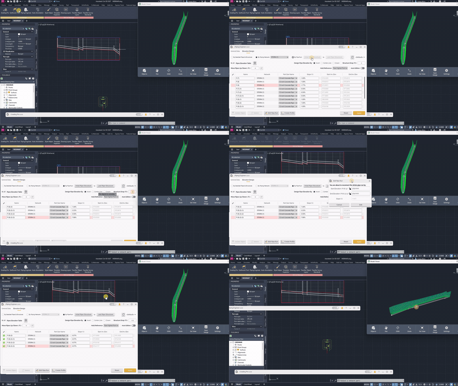
3. Edit Pipe Run
Edit Pipe Run allows you to select a continuous pipe run and edit multiple pipe segments as one set. This is only available for By Pipe Run selection mode, to define the initial and last pipe or structure in the run.
How It Works:
- Select By Pipe Run in the selection mode options.
- Pick the Initial Pipe/Structure and Last Pipe/Structure to define the run range.
- Set the Structure Drop value before editing elevations (if needed).
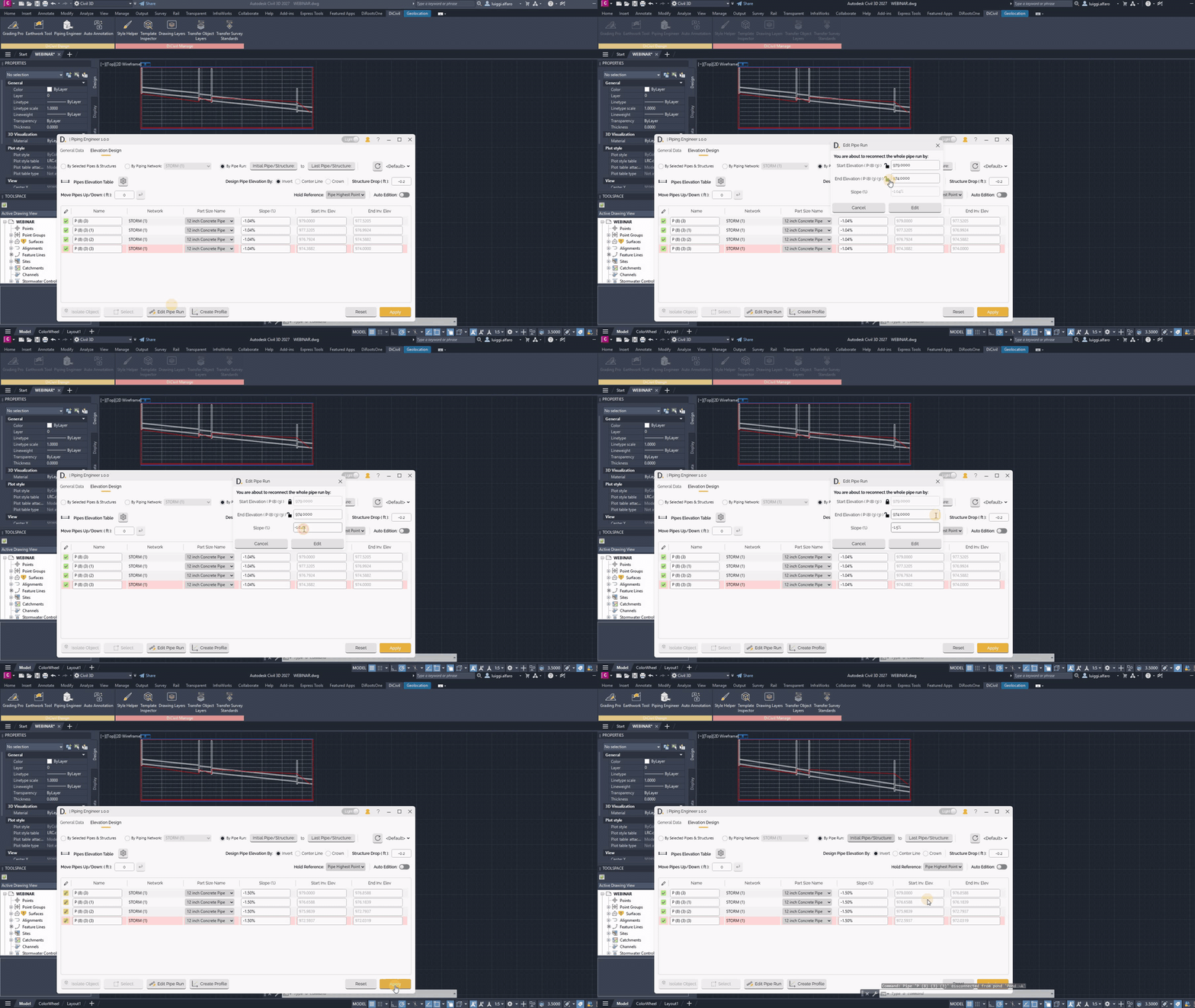
- Lock the start or end to control which elevation reference is maintained during the edit.
- Edit Start Elevation, End Elevation, and Slope for the selected run.
- Click Apply to update the full run in one step.
Usage:
- Use Edit Pipe Run when you need to adjust elevations for a connected sequence of pipes.
- Structure drop is applied at each structure location along the run based on flow direction.
Example: Edit Pipe Run by Start and End Elevation
 Note: the version on the image may not reflect the latest version of DiCivil Package.
Example: Edit Pipe Run Locking Top Reference
 Note: the version on the image may not reflect the latest version of DiCivil Package.
Create Network Profile View
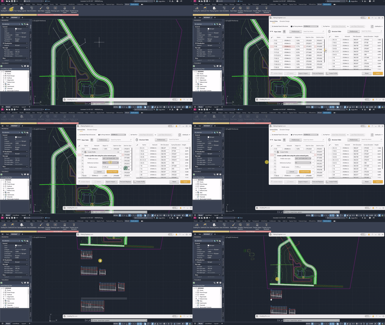
Piping Engineer can generate profile views directly from a pipe network, including branched networks with multiple runs.
Overview
Create Profile allows you to:
- Generate multiple profile views from a selected pipe network in one workflow.
- Split branches at common structures so each run is displayed in its own profile.
- Sort profile sections by flow direction so pipes appear in the correct sequence.
- Include selected surfaces in the generated profiles.
- Place the generated profile views in the drawing with an insertion point.
Workflow
- Open Piping Engineer - From the DiRoots tab.
- Select the piping network - Choose the network to create the profile view.
- Add surfaces - Select the surfaces you want to display in the profiles (if needed).
- Create Profile - Click the Create Profile button.
- Place profiles - Pick the insertion point in the drawing.
- Review results - Verify the generated profile views for each branch.
Usage
- Use Create Profile when you need quick profile layouts for design review or annotation.
- Branched networks are automatically separated at shared structures.
 Note: the version on the image may not reflect the latest version of DiCivil Package.
Workflow Examples
Example 1: Adjusting Multiple Pipes Slope with Auto Flow Edition
- Identify pipes that need adjustment and select them.
- Set Hold Reference. Set the hold reference to the highest point of edited pipes.
- Enable Auto Flow Edition to automatically adjust pipes near the edited ones.
- Set pipe new values. Enter new slope in multiple pipes (e.g. 4%).
- Apply changes. The system adjusts selected pipes and automatically adjusts nearby pipes to maintain system connectivity.

Note: the version on the image may not reflect the latest version of DiCivil Package.
Example 2: Adjusting Multiple Pipes Slope with Auto Flow Edition
- Identify pipes that need adjustment and select them.
- Set Hold Reference. Set the hold reference to the lowest point of edited pipes.
- Enable Auto Flow Edition to automatically adjust pipes near the edited ones.
- Set pipe new values. Enter new slope in multiple pipes (e.g. 3%).
- Apply changes. The system adjusts selected pipes and automatically adjusts nearby pipes to maintain system connectivity.
 Note: the version on the image may not reflect the latest version of DiCivil Package.
Example 3: Moving System Down While Preserving Slopes
- Identify pipes to modify and select them. In this case the first pipe or pipes of the system to move up or down.
- Set Hold Reference and Auto Flow Edition. Set the hold reference to “Hold Slope”. Disable Auto Flow Edition to modify only selected elements.
- Modify elevation (e.g. from 649 to 648 - moving system up 1 units).
- Apply changes. The system moves up while preserving all slopes.

Note: the version on the image may not reflect the latest version of DiCivil Package.
Example 4: Moving Pipes Up/Down with Delta Value
- Identify pipes to move and select them.
- Set Hold Reference. Set the hold reference to “Hold Slope” to preserve pipe slopes during movement.
- Input delta value. Enter the desired movement value directly (e.g., +2.5 to move up 2.5 units, or -1.5 to move down 1.5 units).
- Apply changes. The selected pipes are moved up or down by the specified delta value while preserving all slopes.

Note: the version on the image may not reflect the latest version of DiCivil Package.
Example 5: Editing Pipe Holding Start or End Reference
This example demonstrates how to edit a pipe while holding either the start or end elevation reference. You can modify either the slope or the elevation while maintaining the selected reference point.
- Identify specific pipe to modify.
- Set Hold Reference. Set the hold reference to “Pipe Start” or “Pipe End” to maintain the reference point elevation.
- Set Auto Flow Edition. Disable Auto Flow Edition to modify only selected elements.
- Modify pipe values:
- To modify slope: Enter new slope value. The pipe slope is adjusted while the start or end elevation remains fixed.
- To modify elevation: Enter new elevation value. The elevation is adjusted while maintaining the selected reference point (start or end).
- Apply changes. Selected pipes are modified without affecting the rest of the system.
 Note: the version on the image may not reflect the latest version of DiCivil Package.